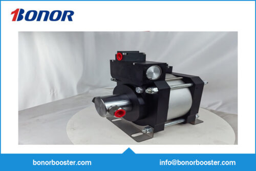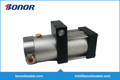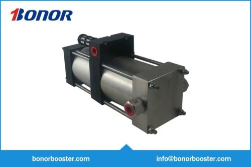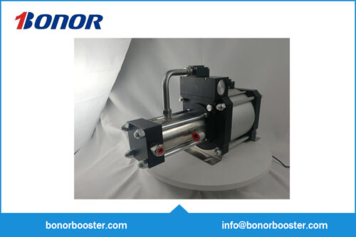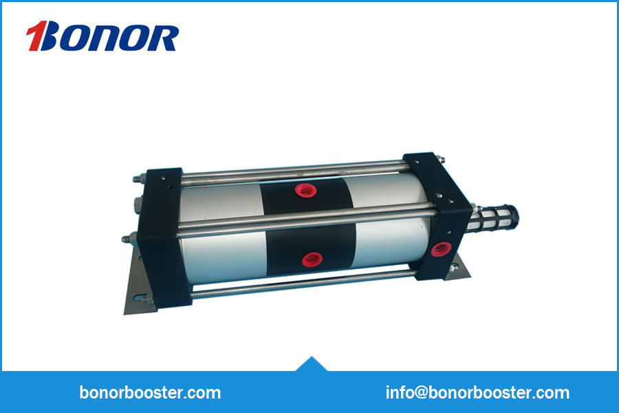
Description
Technical Parameters
- Drive Source: Clean compressed air
- Pneumatic Control System
- Drive Compressed Air Pressure: 1-8 bar (recommended drive pressure < 8 bar)
- Pressure Boost Ratio: 2:1
- Maximum Flow Rate: 580 L/min
- Maximum Air Outlet Pressure: 16 bar
- Suitable Medium: Clean air
- Minimum Inlet Pressure: 1 bar
Application
For example, in production workshops, compressed air is supplied to various gas-consuming points (such as pneumatic tools and machine tools) through pipelines. When the air pressure at the gas-consuming points is unstable or lower than the required level, using an air booster pump to increase the pressure is an economical and effective method. When the air compressor can only provide a maximum pressure of 0.8 Mpa, the A16K-02 model can double the pressure to a maximum of 1.6 Mpa.
The model of the air booster pump should be selected according to the gas supply pressure and required flow rate.
| Model | Pressure Ratio | Maximum Outlet Pressure (bar/psi) | Outlet Pressure Calculation (Driving air pressure 6 bar, inlet & outlet pressure in brackets) | Reference Flow Rate (LN/min) | Internal Thread Interface & Size (Driving/Inlet/Outlet) | Weight (Kg) |
| A16K-02 | 1:2 | 16(232) | pL+pA | 580(6-8) | ZG3/8/ZG3/8/ZG3/8 | 2.6 |
| A32K-02 | 1:2 | 16(232) | pL+pA | 1200(6-8) | ZG1/2/ZG1/2/ZG1/2 | 14 |
| A32K-2D | 1:1.6 | 20(290) | 1.6pL+pA | 960(6-14) | ZG1/2/NPT1/2/NPT1/2 | 17 |
| A32K-3D | 1:2.5 | 28(406) | 2.5pL+pA | 280(6-20) | ZG1/2/NPT1/2/NPT1/2 | 17 |
| A16K-04 | 1:4 | 32(264) | 4pL | 50(6-8) | ZG3/8/NPT3/8/NPT3/8 | 2.5 |
| A32K-05D | 1:4 | 40(580) | 4pL+pA | 420(6-16) | ZG1/2/NPT1/2/NPT1/2 | 15 |
| A32K-05A | 1:5 | 48(696) | 5pL+pA | 360(6-30) | ZG1/2/NPT1/2/NPT1/2 | 16 |
Parameter Description
- Pressure Boost Ratio = Area Ratio of Drive Piston to Boost Piston;
- The maximum outlet pressure is calculated based on a single gas source (pL=pA);
- The reference flow rate is the standard volumetric flow rate when the drive air pressure is 6 bar.
Model Selection Suggestion
Select the corresponding model according to the matching of the gas supply pressure and the required flow rate.
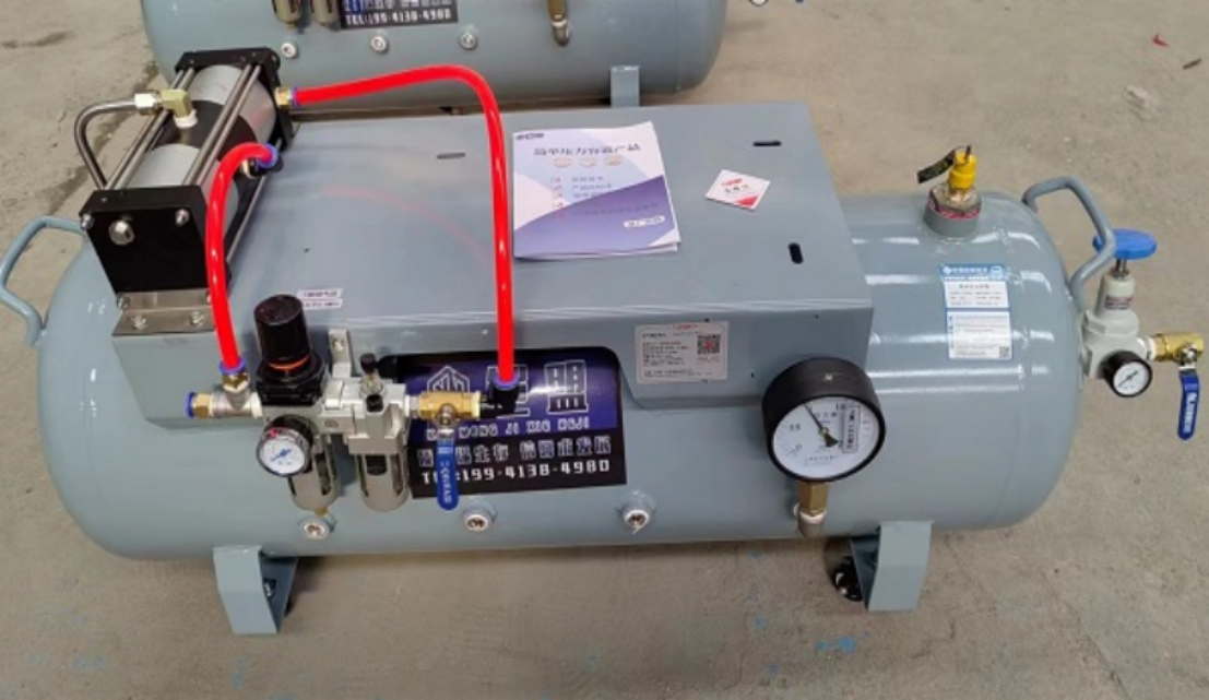
For easier adjustment of the gas supply pressure, the typical usage method is illustrated in the diagram below.
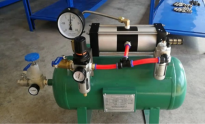
The entire unit consists of an air booster pump, a dual-unit pressure regulating valve, and a pressure reducing valve.
The gas boosted by the air booster pump is stored in an air tank. The operating pressure is set by adjusting the pressure reducing valve at the tank outlet.
When the pressure inside the tank reaches its maximum, the pump automatically stops working. When the pressure drops due to the use of gas at the outlet,
the pump automatically starts working, pressurizes to the maximum pressure, and then automatically stops.
The size of the air tank can be matched according to usage requirements. The upper middle diagram shows 20 liters, and the lower diagram shows 100 liters.