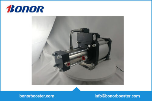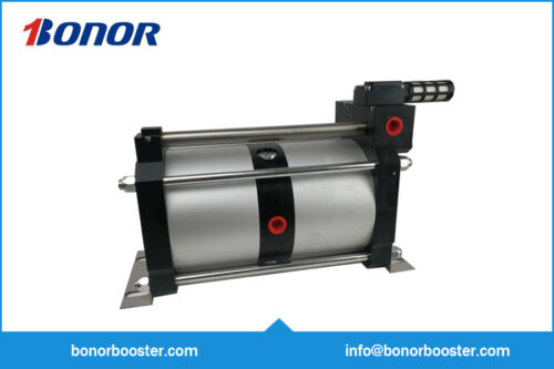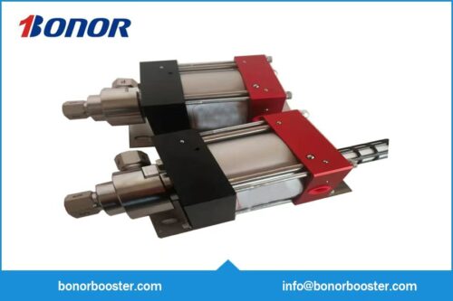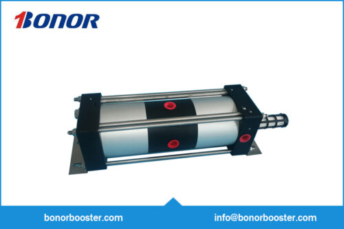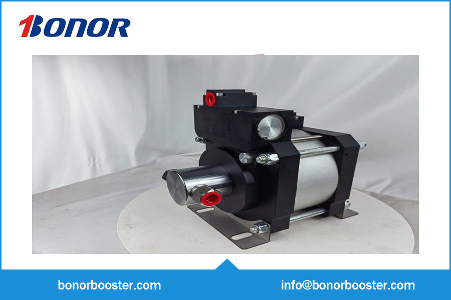
The A32Y Single-Acting Pneumatic Hydraulic Booster Pump is built for air-driven hydraulic pressure generation. Displacement per stroke sets the fill time, which is quoted against the volume you pressurise.
Description
Core Description of A32Y Series Booster Pumps
Ⅰ.Medium Adaptability & Customization
- Basic Adaptability: Oil and water media
- Special Media: Wetted/sealing materials can be customized; an isolation section can be added for chemical media to avoid risks
Ⅱ.Core Design Features
- Large Displacement Advantage: Drive cylinder bore diameter of 160mm; larger high-pressure piston area at the same pressure ratio → higher displacement and flow rate
- Single-Acting Structure: Only one high-pressure cylinder; one suction-discharge cycle is completed per piston reciprocation
- Air Pressure Characteristics: Maximum drive air pressure ≤ 8bar; extremely low starting pressure → sensitive pressure compensation and rapid response
III. Material & Model Rules
- A32Y-04/-05/-06/-10: High-pressure cylinder (stainless steel); high-pressure end cap/piston (aluminum alloy)
- A32Y-16 to -400: All wetted materials are stainless steel
- Model Suffix Meaning: Represents pressure ratio; Maximum outlet pressure = Drive air pressure × Pressure ratio
The table below lists key parameters of 4 mainstream models in the A32Y series:
| Model | Cylinder Bore Diameter | Boost Displacement | Air Consumption Displacement | Weight |
| A32Y-04 | 80mm | 502cm³ | 2009cm³ | 12kg |
| A32Y-05 | 70mm | 192cm³ | 2009cm³ | 12kg |
| A32Y-06 | 63mm | 310cm³ | 2009cm³ | 12kg |
| A32Y-10 | 50mm | 196cm³ | 2009cm³ | 12kg |
The displacement of A32Y-04, 05, 06, and 10 can be increased by lengthening the stroke.
Applications of the pneumatic hydraulic booster pump
Hydraulic power without a hydraulic power unit is the point of the A32Y Single-Acting Pneumatic Hydraulic Booster Pump: compressed air in, high-pressure liquid out, and a pump that holds pressure silently once it reaches the set point.
- Mobile and offshore equipment — pressure generation where only air is available.
- Clamping and press fitting — holding hydraulic clamps, presses and assembly fixtures.
- Valve actuation testing — pressurising actuator cylinders with a controlled, recorded pressure.
What to specify before we build yours
- Outlet pressure and ratio — derived from the drive air pressure available at the installation point.
- Wetted materials and medium — water, oil, glycol or a chemical; seals and body material follow the medium.
- Displacement per stroke — sets the fill time for the volume you need to pressurise.
- Control — manual regulator, or a pressure switch that stops the pump at the set point.
How to choose a pneumatic hydraulic booster pump
These pumps are simple, but two mistakes are common: sizing on stall pressure and ignoring the medium.
- Size on fill time. A pump that reaches 200 bar in ten minutes is fine for holding pressure and useless for a test that needs to fill a 50-litre vessel each cycle. Check the displacement against the volume.
- Match the seals to the medium. Water with glycol, hydraulic oil and a chemical additive each need a different seal. The wrong seal shows up as a leak after a few hundred cycles, not at commissioning.
- Provide a relief path. An air-driven pump can generate full pressure against a closed valve. A relief valve on the outlet is not optional.
Frequently asked questions
What outlet pressure can an air-driven pump reach?
Ratios up to about 1:100 are available, so with 6 bar drive air the theoretical maximum is several hundred bar; in practice the achievable pressure is lower because of friction. The ratio is chosen from the drive air you have and the pressure you need.
Which liquids are compatible with the wetted parts?
Water, water-glycol, hydraulic oil and most non-aggressive chemicals are standard with the appropriate seal. Aggressive chemicals need a body and seal review, and food-grade applications need a different lubricant.
How is the pressure held steady?
The pump stalls when the outlet reaches the set pressure and restarts when it drops, so the pressure is held within the band of the switch or regulator. Adding an accumulator tightens that band.
Related equipment and further reading
- A16Y Pneumatic Hydraulic Booster Pump
- All Pneumatic Hydraulic Booster Pump models and specifications
- How does an air booster pump work
- Key features of an air booster pump
Need a pressure range, fixture or test standard that is not listed here? Send the specimen list and the standard you test to and we will come back with a configuration and a price within one working day.