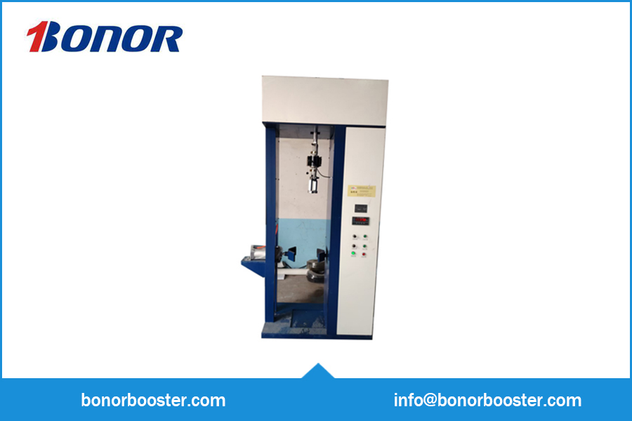
Applicable Cylinder Diameter Range: 130–250 mm
Height Range: (Latest Model: 1140–1510 mm)
Air Source Pressure: 0.6–0.8 MPa
Number of Workstations: 1
Overall Dimensions: 1430 × 600 × 2935 mm
Power Supply: 380 V / 50 Hz
Applicable Cylinder Diameter Range: 130–250 mm
Height Range: (Latest Model: 1140–1510 mm)
Air Source Pressure: 0.6–0.8 MPa
Number of Workstations: 1
Overall Dimensions: 1430 × 600 × 2935 mm
Power Supply: 380 V / 50 Hz
Instruction Manual
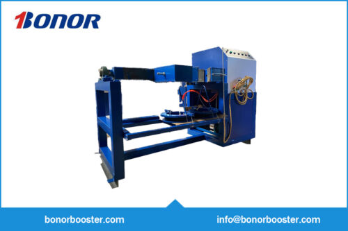
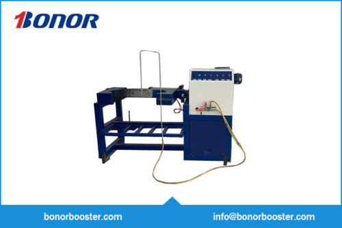
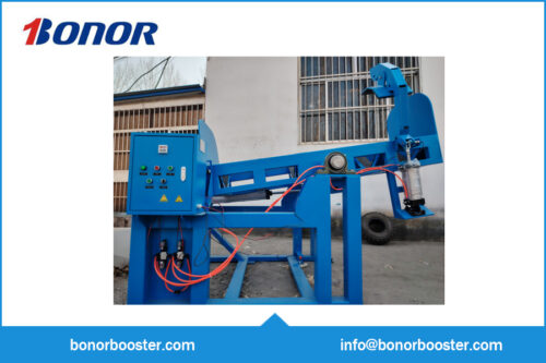
The Automatic Cylinder Valve Loading and Unloading Machine has been designed and manufactured in accordance with national regulations strictly prohibiting the use of pipe wrenches or other tools liable to damage the cylinder body during the loading and unloading of cylinder valves, as well as to meet the operational requirements of cylinder manufacturers, inspection stations, and similar facilities engaged in such tasks.
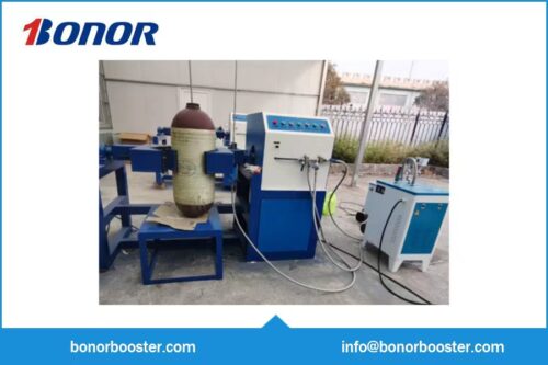
Suitable for the installation and removal of cylinder valves on various gas cylinders with diameters ranging from φ219 mm to φ250 mm. Features simple operation and reliable performance.
III. Equipment Operating Environment and Safety Safeguards
Applicable Cylinder Diameter Range: 130–250 mm
Height Range: (Latest Model: 1140–1510 mm)
Air Source Pressure: 0.6–0.8 MPa
Number of Workstations: 1
Overall Dimensions: 1430 × 600 × 2935 mm
Power Supply: 380 V / 50 Hz
The work site must be free of excessive dust, flammable substances, and corrosive gases.
Under the aforementioned operating conditions, the equipment will function normally while maintaining full safety protection.
This equipment has been strictly designed and manufactured in accordance with relevant national professional standards. It generates no environmental pollution, and all electrical insulation properties underwent rigorous testing prior to leaving the factory, ensuring full compliance with applicable standards.
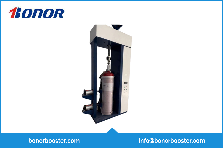
This machine consists of a frame, a clamping device, a bottle-flipping device, a transmission mechanism, an electrical control system, and other components. Their primary functions are as follows:
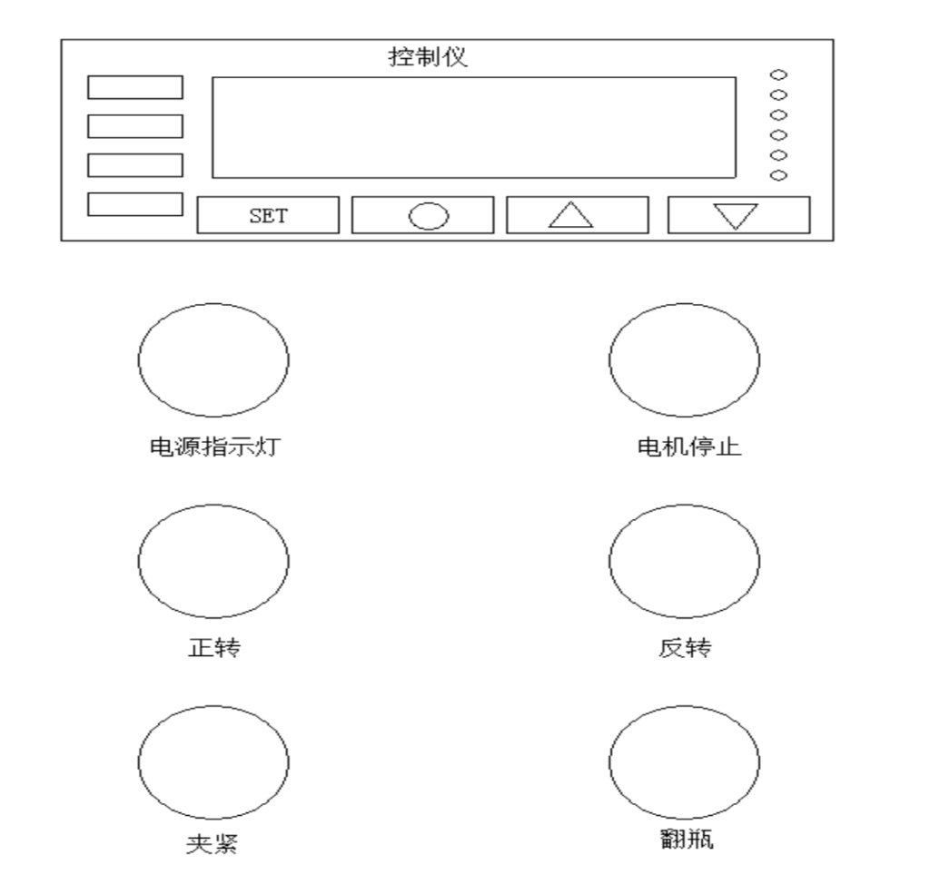
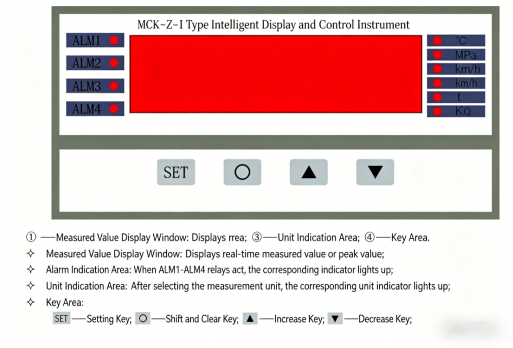
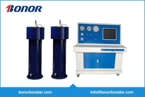
While in measurement mode, press the SET button; the first two digits of the display window will show “LC,” while the last two digits will display the password. Press the “Increase” button to set the last two digits to the password for the first parameter group—”10″—to enter the alarm parameter configuration interface. Press the SET button repeatedly until the desired display appears in the window. Then, press the “O” button to select the specific digit you wish to modify. Note that the current display mode utilizes a single decimal place; therefore, if your target value is 200 N·m, the numerical value you must enter during configuration should be 2000. Once modifications are complete, continue pressing the SET button until the display window reverts to showing the current measured value; the configuration process is now finished
After-Sales Service Terms
Our company is available at any time—via telephone, email, or online channels—to answer customer inquiries regarding our products, as well as their usage, maintenance, and repair.
Effective from the date of equipment purchase (i.e., the date the purchase contract is signed), all products sold by our company are entitled to a one-year free warranty service. During this period, provided the issue is not caused by human factors (such as failure to operate or maintain the product in accordance with the user manual, unauthorized structural modifications, etc.), you will not be required to pay for any parts or labor costs necessary for repairs should any malfunction arise due to inherent product quality issues.
If a product malfunctions and requires repair more than one year after the date of purchase (i.e., the date the purchase contract was signed), you will be required to pay only for the necessary replacement parts and reasonable labor costs for the repair.
Additional Notes on After-Sales Service:
Additional Notes Regarding After-Sales Service: