Description
I:Introduction to the Test Apparatus
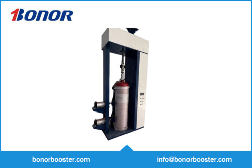
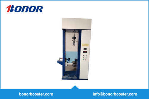
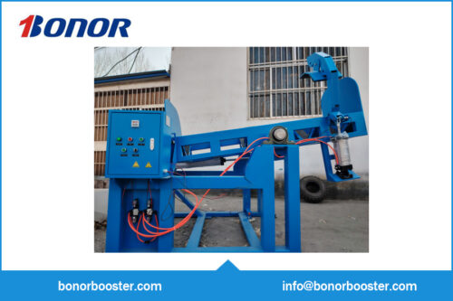
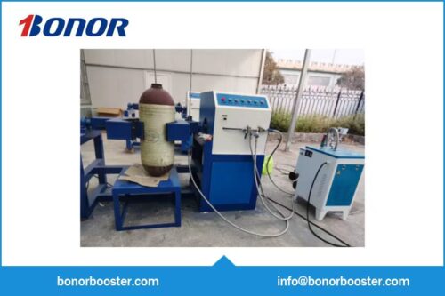
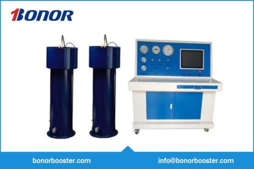
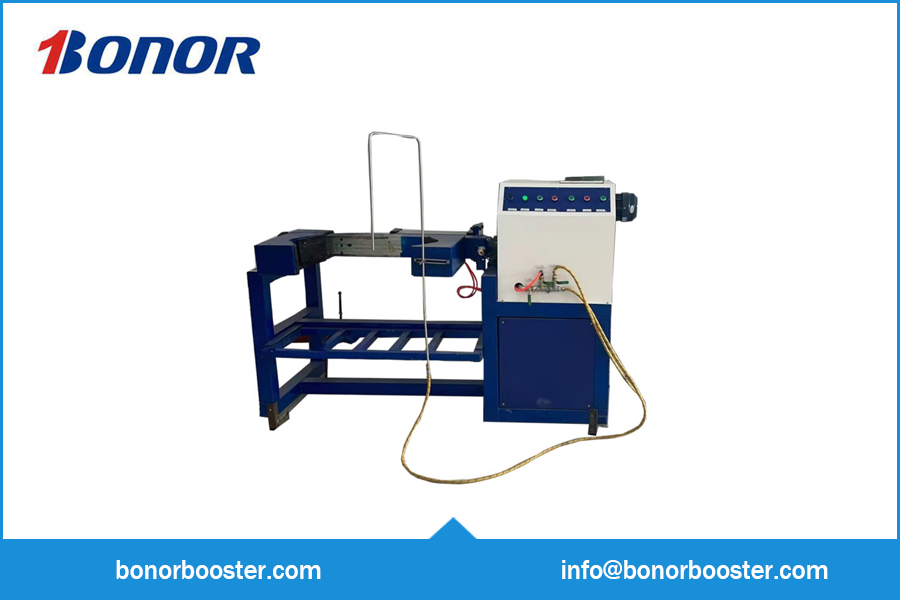
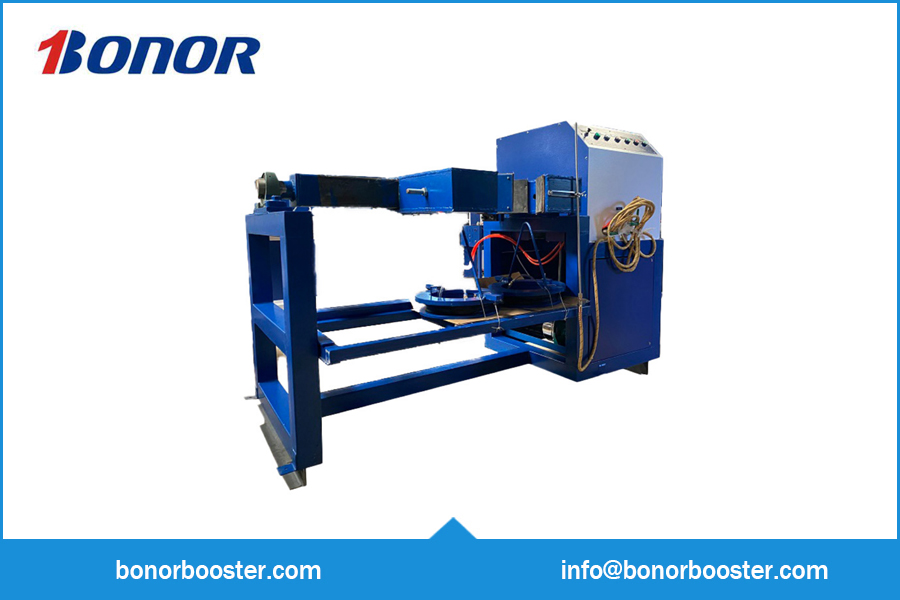
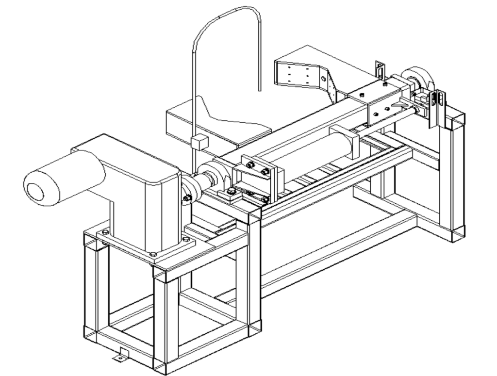
The Integrated Fire Cylinder Drying, Tilting, and Cleaning Machine (hereinafter referred to as “the Equipment”) is designed for the internal draining, cleaning, and drying of various types of steel gas cylinders and storage tanks during the stages of manufacturing, incoming inspection, outgoing inspection, and inspection assessment.
The Equipment consists of a steam generator, a 180° tilting stand, an electrical control cabinet, a high-pressure cleaning pump, and associated steam and water piping, valves, and connections.
II : Main Technical Parameters
- Steam Generator Power: 9 kW
- Reducer Power: 1.5 kW
- High-Pressure Cleaning Pump Power: 2 kW
- Power Supply: 380 V / 50 Hz
- Number of Workstations: 1
- Overall Dimensions: 2015 mm (Length) × 900 mm (Width) × 1250 mm (Height)
III. Installation
- Securely fasten the equipment using expansion bolts, based on the user’s actual installation site.
- Based on the installation location, prepare a drainage pit or channel for the cylinder cleaning and rinsing process.
- Determine whether to utilize the adjustable support bracket based on the height of the gas cylinder.
- For cylinders exceeding 1000 mm in height, remove the adjustable support bracket; for cylinders under 1000 mm, utilize the adjustable support bracket.
- Connect the external power supply, air supply lines, and water supply lines.
- Connect the outlet line of the high-pressure cleaning pump to the quick-connect fitting on the high-pressure hose outlet.
- Connect the outlet line of the steam generator to the silicone hose outlet valve and quick-connect fitting.
- Connect the inlet line of the stainless steel insertion tube to the high-pressure quick-connect fitting.
- Install the pressure gauge and safety valve for the steam generator.
- The safety valve outlet shall be routed outdoors, minimizing the use of elbows wherever possible;
- The drain piping shall be routed outdoors or connected to a drainage system, minimizing the use of elbows wherever possible;
- The steam generator water inlet shall be connected to a purified water source (refer to the steam generator manual for specific details);
Operating Procedures for the Integrated Fire Cylinder Drying, Rotating, and Cleaning Machine
- Perform preheating in accordance with the steam generator’s operating instructions.
- Based on the height of the gas cylinder, determine whether to utilize the adjustable support bracket (refer to the installation instructions).
- Position the gas cylinder—which is awaiting cleaning and drying—between the clamping seats, ensuring it makes contact with the fixed clamping seat.
- Rotate the manual valve to clamp the gas cylinder:
1) The manual valve is a 3-position, 4-way directional control valve featuring four ports labeled P, R, A, and B; all ports have a size of 3/8 inch. Port P serves as the air inlet, while Port R serves as the exhaust outlet; a silencer is connected to the exhaust outlet.
2) To adjust the cylinder’s operating speed: Loosen the lock nut, then turn the adjustment nut clockwise to decrease the clamping speed; conversely, turn it counter-clockwise to increase the clamping speed.
3) Ports A and B are connected to the cylinder’s air intake ports, which also feature a 1/2-inch thread size.
4) The manual rotary valve is a 3-position valve featuring a closed-center position, allowing the clamping action to be halted at any time. Rotating the valve handle up or down controls the extension and retraction of the cylinder, thereby executing the gas cylinder clamping operation.
5) Insert the stainless steel probe tube into the gas cylinder under inspection; rotate the knob on the magnetic base to the “0N” position, then utilize the magnetic force to secure the probe tube firmly to any desired location on the cylinder.
6) Connect the quick-connect fitting on the high-pressure outlet of the cleaning pump to the quick-connect fitting on the inlet of the probe tube.
7) Click the “Flip” button to invert the gas cylinder, positioning it upside down with the valve opening facing downward.
- Activate the high-pressure water pump switch to clean the interior of the gas cylinder.
- Once cleaning is complete, disconnect the high-pressure quick-connect fitting from the cleaning pump and attach the quick-connect fitting from the steam silicone hose outlet.
- Open the valve on the steam outlet line (adjusting to the required steam temperature and pressure) to steam-dry the interior of the cylinder.
- Once the steam purging process is complete, close the steam outlet control valve.
- After the steam has cooled, disconnect the high-pressure quick-connect fitting from the steam silicone hose outlet (Caution: Risk of burns!).
- Press the “Return” button to rotate the gas cylinder back to its starting position.
- Turn the manual valve to release the clamping assembly.
- Remove the inspected gas cylinder, thereby completing the internal cleaning and drying process.
- Depending on the specific situation, close the control ball valve once the drying process is finished.
- Remove the dried gas cylinder, taking care to ensure there is no risk of burns.
Note: During operation, exercise extreme caution to avoid steam burns!
- Fully Automatic Steam Generator (Component of the Machine) — Operating Instructions:
- Key Technical Parameters
Rated Electric Power: 9 kW; Voltage: 380 V; Rated Working Pressure: 0.7 MPa; Saturated Steam Temperature: 171°C; Rated Steam Evaporation Capacity: 15 kg/h; Normal Water Capacity: 24 L.
- Product Introduction
This product is a fully automatic, electrically heated steam generator. It features a compact and rational structure, small size, ease of mobility, minimal footprint, ease of cleaning, non-polluting operation, high thermal efficiency, and advantages such as time and labor savings.
- Installation Instructions
1) As the water capacity of this electric steam generator is less than 30 liters, installation may be performed by the user or entrusted to our company’s installation team, in accordance with relevant regulations and standards. It does not require the construction of a dedicated boiler room. During installation, the unit should be physically separated from the area where the steam is utilized; furthermore, ensure that the discharge direction of the safety valve is positioned away from any personnel.
2) Installation Precautions
- a) The safety valve must be installed in a vertical position. No steam outlet pipes or valves intended for drawing steam shall be installed between the safety valve and the boiler.
- b) The number of elbows (bends) in the blowdown pipe should be minimized as much as possible.
- c) Adequate lighting must be provided at the locations of the pressure gauge and the water level indicator.
- Operating Instructions
1) Automatic Control Instructions
- a) Pressure Control: When the operating pressure reaches the high pressure setpoint, the electric heating elements automatically cut off power and cease heating; the heating indicator light turns off. When the operating pressure drops to the low pressure setpoint, the electric heating elements automatically resume heating; the heating indicator light turns on.
- b) Water Level Control: When the water level in the boiler drum rises to the maximum level, the water pump automatically cuts off power and stops supplying water; the water supply indicator light turns off. When the water level drops to the minimum level, the water pump automatically powers on to supply water to the boiler drum; the water supply indicator light turns on. If external water supply interruption, water pump failure, or similar issues prevent water from being supplied to the boiler drum, the electric heating elements will simultaneously cut off power and cease heating; the heating indicator light turns off. In such instances, the operator must immediately shut down the boiler to investigate and identify the cause of the fault, and must not resume operation until the fault has been fully resolved.
2) The boiler water quality must comply with the GB1576-2001 standard, “Water Quality for Industrial Boilers.” Under normal operating conditions, purified potable water should be used as the primary water source.
3) Operation Procedures:
- a) Open the water inlet valve, connect the generator to the power supply, and fill the boiler drum with water until the normal water level is reached; then, close the steam outlet valve and the blowdown valve.
- b) The set pressure of the safety valve has been pre-adjusted by the manufacturer; the user shall not attempt to adjust it independently. If the safety valve is found to be malfunctioning, it must be replaced with a new one. Similarly, the high-pressure limit and operating pressure settings of the pressure controller have been pre-adjusted by the manufacturer; the user shall not attempt to adjust them independently.
- c) Heating: Switch on the main power supply; the operation indicator light will illuminate, and the boiler water heating process will commence.
- d) Steam Supply: Once the internal pressure rises to the designated operating pressure, open the steam outlet valve to initiate steam supply. Prior to supplying steam, the steam delivery piping should be preheated; subsequently, transition to full steam supply operation.
- e) During normal operation, perform periodic blowdown in accordance with relevant regulations (at least once every 8 hours) and promptly clean any scale accumulation from the water level probes using sandpaper.
- f) Unauthorized dismantling of the safety valve is strictly prohibited; unauthorized modification or the use of plugs to permanently seal it off is also strictly prohibited. Unauthorized alteration of pressure control functions and parameters is strictly prohibited.
- g) The siphon tube (pigtail) connected to the pressure gauge must be removed and cleaned periodically.
4) Shutdown Procedures: When shutting down the unit, the power supply to the generator must be disconnected, and the boiler water drained.
- a) During the shutdown period, “dry preservation” methods should be employed.
- b) If the unit remains shut down for more than six months, a hydrostatic test must be performed prior to resuming operation.
- c) This generator requires an external inspection and a hydrostatic test once annually.
- d) When repairing or replacing parts, the main power supply must be disconnected and all residual steam vented; performing work while the unit is energized or under pressure is strictly prohibited.
5) Operational Precautions
- a) This unit must be operated by designated personnel only. Operators must thoroughly read the instruction manual and strictly adhere to the warning labels and operating instructions affixed to the exterior of the machine.
- b) Connect the unit to the municipal water supply and fill the water tank to the maximum level.
- c) Connect the main power supply and ensure that the grounding wire is securely connected to the unit’s casing.
- d) When using a three-phase power supply, connect the wire marked “N” to the power supply’s neutral line, and connect the three wires marked “Live” to the A, B, and C phase lines of the power supply, respectively.
- e) Open the air release screw on the water pump (located on the pump head); wait until water begins to flow out, then tighten the screw.
- f) Turn on the machine’s power switch; wait a few minutes for the water level to automatically reach the required position, at which point the water filling process will stop automatically. g) Initiate the heating process; wait until the pressure reaches 0.4 MPa, at which point the heating will stop automatically.
- h) Before starting the machine each time, verify that the power supply is functioning normally and ensure that the water tank has been sufficiently filled.
- i) Whenever shutting down the machine, promptly drain the water and steam from the boiler’s inner chamber and switch off the main power supply. Failure to do so will cause the residual steam inside the machine to cool down and condense into liquid (creating a “false pressure” reading); consequently, when the machine is restarted the following day, the pressure gauge will rise rapidly, but opening the steam valve will result only in the discharge of water.
- j) During operation, ensure that blowdown (draining of impurities) is performed in a timely manner—ideally twice daily. Blowdown should be conducted while the boiler is under pressure (approximately 0.15 MPa); this practice is essential for preventing blockages within the piping system. Ensure that the blowdown discharge pipe is securely connected to prevent scalding injuries.