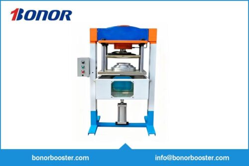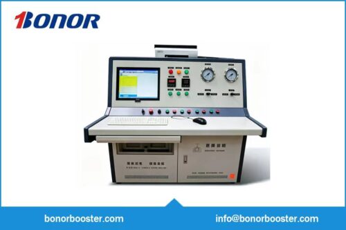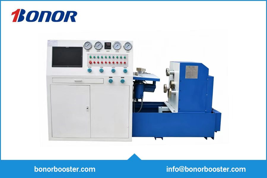
The clamping type valve test bench developed by Jinan Bonor Technology Co., Ltd. is used for pressure performance tests including tightness test and valve body strength test of straight-through flange-connected valves. It complies with standards such as GB/T 13927-2008 Pressure Test for General Valves, JB/T 9092-99 Valve Inspection and Test and American Standard API 598, to conduct strength test, seat tightness test and backseat tightness test for flange-type valves.
Description
一. Technical Parameters
| Item | Specification |
| Applicable valve nominal diameter (mm) | DN80 ~ DN300 |
| Max. test pressure for full bore | 16.0 MPa |
| Opening range of movable frame (mm) | 200 ~ 1080 |
| Cylinder clamping force | 211 Ton |
| Hydraulic system Flow rate | 25 L/min |
| Hydraulic system High pressure boosting range | 3.0 ~ 31.5 MPa |
| Motor power (kw) | 3.0 |
| Power supply | 380V/50HZ |
二. Features
- Clamping by jaw gripping flange, fully meets requirements of GB/T13927-2008, JB/T9092-99 and API598.
- The left clamping unit is a movable frame that can slide horizontally, adapting to valves with different lengths.
- The right rotary turntable supports 90° rotation, convenient for valve air tightness inspection.
- Audio & visual alarm function. After pressure holding phase, the equipment triggers buzzer and indicator light to remind test status.
- Water pipeline adopts 304 stainless steel. The bench is equipped with high & low pressure stainless steel water pumps.
- Low-pressure gas tightness test for valves: A bubble counter is equipped within the PLC data management system. A bubble detection unit is installed at the valve outlet. When leakage occurs on sealing surfaces, gas flows from valve inlet to outlet and enters the bubble detector to generate bubbles in water. The infrared sensor counts bubbles and transmits data to PLC. The leakage rate is calculated according to bubble quantity per minute. The bubble counter satisfies low-pressure gas tightness test requirements specified in ANSI/FCI 70-2006, ANSI B16.104 and GB/T4213-2008.
What a safety valve test bench does in production
Repair shops live by turnaround time: a valve on the bench is a valve not protecting a plant. The Clamping-type valve test bench is arranged so clamping, pressurisation and reading happen without fumbling — the valve goes on, the test runs, the certificate prints. The primary workload here is clamping-type testing, so fixtures and ramp logic are prepared for it from the factory; other valve families slot in with additional fixtures.
- Refinery turnaround support — high volumes of PSVs reset and verified on schedule with full documentation.
- Fire-protection systems — pressure-relief and deluge valves proven before system handover.
- High-volume repair shops — quick-clamp tables sized for the shop's dominant flange classes.
What makes this Clamping-type valve test bench practical is the way it handles the valve: one clamping routine, one pressurisation recipe and one result file, test after test.
What to specify before we build yours
- Test medium — air, nitrogen, steam or water; steam testing requires a steam generator and different safety measures. It is set up here for the valve.
- Valve size and flange standard — the clamping table has to accept the bodies you see most, from small threaded valves to flanged API valves. The setting here follows the valve you run most.
How the standard build is set up here: This unit works with motor power (kw) at 3.0. On this machine power supply is 380v/50hz.
Selecting a safety valve test bench for your line
Safety-valve benches differ less in the pump than in everything around it — clamping, sensing and records. Compare candidates on these points:
- Check the measurement side, not only the pressure side. Lift detection, seat-tightness measurement and temperature compensation decide the quality of the numbers. A transducer and a chart recorder are not equivalent to a proper measurement chain.
- Ask how the bench handles high set points on small inlets. A DN20 valve set at 6.4 MPa behaves differently from a DN150 at 1 MPa, and the fixture plus the sensing range need to cover both ends honestly. Check the accuracy statement at your actual set points, not at mid-scale.
- Fixture fit for the valve. The clamping set is drawn around your valve drawings first, so the part sits square without shimming — and the same fixture family extends to other sizes later.
Frequently asked questions
How close to the stamped set pressure must the valve open?
Codes typically allow a tolerance of plus or minus three percent at the set point, and some standards tighten it further for certain services. The bench does not change the tolerance — it tells you honestly where the valve sits so the adjustment brings it inside. The record shows the as-found and as-left values. On this build the valve is the reference case, and the setting is proven with your samples at commissioning.
How often should safety valves be verified?
The interval comes from your code, your insurer or the equipment owner — commonly once a year for steam plant and between one and five years elsewhere. The bench does not set the interval; it makes each verification cheap and documented enough that the interval is actually kept. The Clamping-type valve test bench quotation states this scope explicitly, item by item.
Related equipment and further reading
- Nuclear Valve Hydrostatic Test Bench
- Breather valve test bench
- Hydraulic Valve Test Bench
- The complete Safety Valve Test Machine line-up
- Accuracy checks without a lab
- Inside a safety valve bench
If your valve type is not described above, send a nameplate photo or the flange drawing and our engineers will confirm coverage and price within one working day.