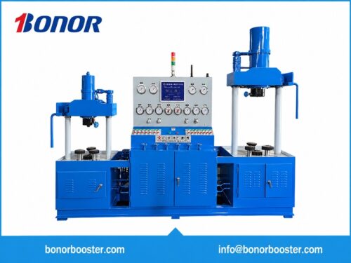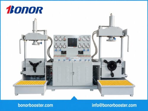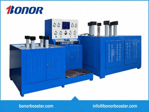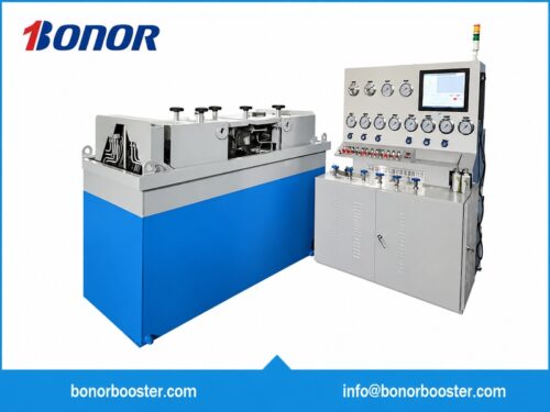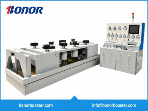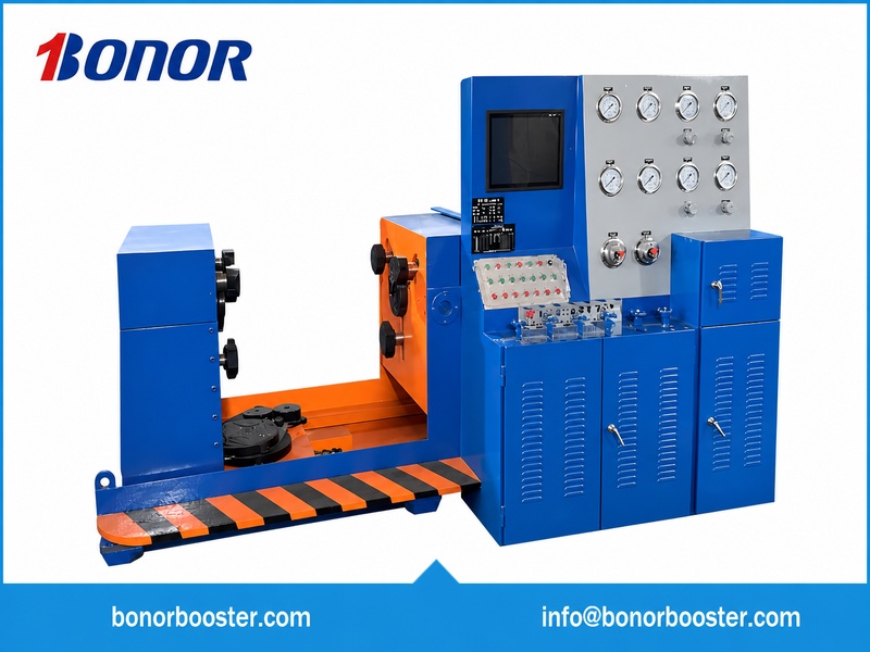
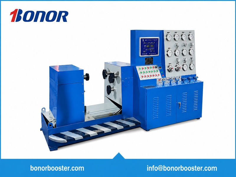
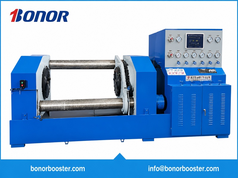
- Suitable for Various Flange-Connected Valves
- Hydraulic Clamping for Reliable Testing
- Water and Gas Pressure Testing
- Custom Solutions for Different Valve Sizes
Horizontal Valve Test Bench
Description
Horizontal Valve Test Bench
Product Introduction
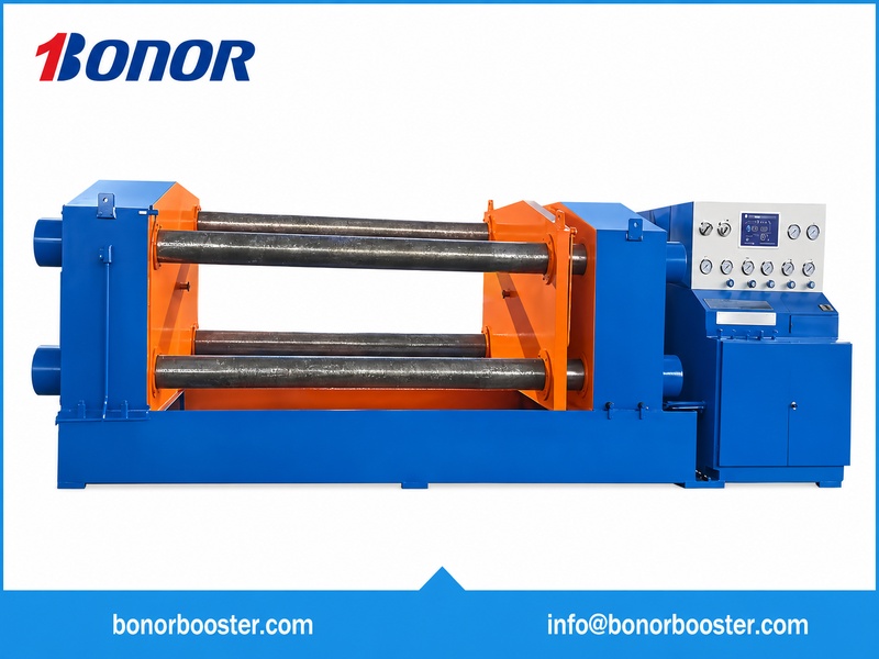
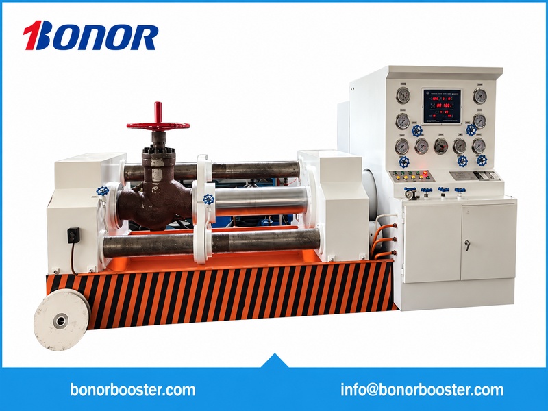
The Horizontal Valve Test Bench is designed for pressure and sealing tests on flange-connected valves, including ball, gate, globe, check, and control valves. Its hydraulic clamping system and dual-pump pressure control provide reliable testing performance and efficient operation.
Suitable for valve manufacturers, testing facilities, and maintenance workshops, the system can be customized to meet different testing requirements.
Horizontal Clamping Valve Test Bench |
Horizontal Clamping Valve Test machine |
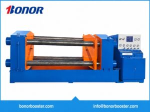
Horizontal Valve Test Bench |
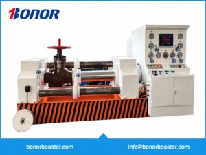
Top Pressure Horizontal Valve Test Bench |
Key Features
1. Wide Range of Valve Applications
Suitable for testing flange-connected ball valves, gate valves, globe valves, check valves, and control valves.
2. Hydraulic Clamping System
The hydraulic claws clamp the back of the valve flange to seal the valve ends, minimizing external forces on the valve body and helping ensure accurate test results.
3. Optional 90° Rotation
The test bench supports 90-degree rotation for flexible valve positioning during testing. Dual-end rotation is available as an option.
4. Water and Gas Testing
Supports both water and gas testing. Test water can be recycled to reduce water consumption and operating costs. Switching between testing media is controlled through pipeline valves.
5. Dual-Pump Pressure Control
A low-pressure, high-flow pump enables rapid pressurization, while a high-pressure pump gradually increases pressure. The system automatically enters the pressure-holding stage when the preset test pressure is reached.
6. Zero-Pressure Safety Protection
The hydraulic clamping mechanism can only be released when the pressure inside the valve cavity has returned to zero, helping prevent accidental release under pressure.
7. Optional Safety and Automation Features
Available options include safety doors, dual-end 90-degree rotation, PLC-based data acquisition, and automated testing systems.
8. Customized Testing Solutions
Custom designs are available to accommodate different valve dimensions, testing pressures, and specific application requirements.
Technical Specifications
| Specification | Unit | A100 | A200 | A300 | A400 | A500 | A600 | A800 | A1000 | A1200 |
|---|---|---|---|---|---|---|---|---|---|---|
| Model | — | DYFJ-A100 | DYFJ-A200 | DYFJ-A300 | DYFJ-A400 | DYFJ-A500 | DYFJ-A600 | DYFJ-A800 | DYFJ-A1000 | DYFJ-A1200 |
| Applicable Valve Size | ||||||||||
| Nominal Valve Size (DN) | mm | 15–100 | 50–200 | 80–300 | 200–400 | 250–500 | 300–600 | 400–800 | 500–1000 | 600–1200 |
| Nominal Pressure Range | MPa | 1.6–32 | 1.6–32 | 1.6–32 | 1.6–32 | 1.0–16 | 1.0–16 | 1.0–16 | 1.0–16 | 1.6–16 |
| Valve Face-to-Face Length | ||||||||||
| Maximum Length | mm | 350 | 550 | 750 | 950 | 991 | 1143 | 1524 | 1727 | 1981 |
| Minimum Length | mm | 130 | 180 | 210 | 330 | 380 | 502 | 610 | 711 | 813 |
| Valve Flange Dimensions | ||||||||||
| Maximum Flange Diameter / Thickness | mm | 265/42 | 405/55 | 530/83 | 670/92 | 775/108 | 890/108 | 1085/108 | 1360/120 | 1575/120 |
| Minimum Flange Diameter / Thickness | mm | 90/12 | 160/16 | 195/20 | 355/26 | 390/28 | 460/32 | 520/32 | 715/34 | 813/120 |
| Moving Frame Opening Distance | ||||||||||
| Maximum Distance | mm | 700 | 850 | 1080 | 1200 | 1400 | 1500 | 2120 | 2350 | 2500 |
| Minimum Distance | mm | 170 | 250 | 300 | 350 | 400 | 450 | 550 | 650 | 850 |
| Clamping Mechanism | ||||||||||
| Axial Stroke | mm | 52 | 62 | 75 | 80 | 90 | 95 | 100 | 105 | 105 |
| Radial Stroke | mm | 125 | 150 | 200 | 230 | 250 | 250 | 340 | 340 | 410 |
| Hydraulic System | ||||||||||
| Rated Hydraulic Pump Pressure | MPa | 6.3 | 6.3 | 6.3 | 6.3 | 6.3 | 6.3 | 6.3 | 6.3 | 6.3 |
| Pump Flow Rate | L/min | 6.3 | 16 | 25 | 25 | 40 | 40 | 63 | 63 | 63 |
| High-Pressure Booster Range | MPa | 3–31.5 | 3–31.5 | 3–31.5 | 3–31.5 | 3–31.5 | 3–31.5 | 3–31.5 | 3–31.5 | 3–31.5 |
| System Pressure Adjustment Range | MPa | 0–6.3 | 0–6.3 | 0–6.3 | 0–6.3 | 0–6.3 | 0–6.3 | 0–6.3 | 0–6.3 | 0–6.3 |
| Power Supply | ||||||||||
| Voltage | V | 380 | 380 | 380 | 380 | 380 | 380 | 380 | 380 | 380 |
| Frequency | Hz | 50 | 50 | 50 | 50 | 50 | 50 | 50 | 50 | 50 |
| Electric Motor | ||||||||||
| Motor Power | kW | 1.5 | 2.2 | 3 | 3 | 5.5 | 5.5 | 7.5 | 7.5 | 7.5 |
| Number of Poles | P | 4 | 6 | 6 | 6 | 6 | 6 | 6 | 6 | 6 |
| Overall Dimensions | ||||||||||
| Length (L) | mm | 2550 | 2820 | 3100 | 3350 | 3750 | 3900 | 5200 | 5500 | 6000 |
| Width (B) | mm | 1230 | 1400 | 1510 | 1750 | 1800 | 1900 | 2400 | 2500 | 3000 |
| Height (H) | mm | 1200 | 1300 | 1350 | 1450 | 1500 | 1650 | 2000 | 2200 | 2300 |
| Machine Weight | kg | 1980 | 2400 | 3000 | 4400 | 5000 | 5600 | 8000 | 12000 | 14000 |
Note: Specifications are based on the provided technical data. Customized configurations may be available upon request.
Applications of the valve test bench
Every industrial valve leaves the factory with two questions attached: does the body hold pressure, and does the closure seal. The Horizontal Valve Test Bench answers both on one fixture, with the clamping, the pressure circuits and the record that a valve test procedure expects.
- Pipeline and EPC contractors — incoming inspection of valves before installation, against API 598 or the project specification.
- Water and HVAC contractors — pressure testing of butterfly, gate and ball valves before commissioning.
- Valve manufacturers — routine shell and seat testing at the end of the assembly line.
What to specify before we build yours
- Valve type and size range — ball, gate, globe, butterfly, check or control; each needs a different clamping and sealing arrangement.
- Pressure class — the bench must exceed the highest class in scope, usually with a margin for the shell test multiplier.
- Test medium — water, air or gas; the seat-leak measurement method changes with the medium.
- Test sequence automation — manual valve switching, or a programme that runs shell, seat A and seat B in order and logs each result.
How to choose a valve test bench
The fixture, not the pump, is what makes a valve bench usable day after day:
- Look at how the valve is clamped. End-loading rams seal against the flange faces; a clamping table holds the body from outside. End-loading is faster for flanged valves, a table is more flexible for threaded and welded-end bodies.
- Confirm both seat directions are testable. A seat test has to be repeated on the upstream and downstream side of the closure; if the fixture cannot isolate each side, the operator will improvise with blind flanges and lose the cycle time.
- Decide how leakage is measured. Water gives a visible drip count, air gives a bubble count or a pressure decay, gas gives a flow reading. The bench should report the unit your standard specifies.
Frequently asked questions
What is the difference between a shell test and a seat test?
A shell test pressurises the whole valve body with the closure open or removed, to prove the pressure boundary. A seat test pressurises one side of the closed closure and measures leakage past the seat. Both are required by API 598 and equivalent standards, and they use different circuits.
Can the bench test both metal-seated and soft-seated valves?
Yes. The acceptance criteria differ — metal seats allow a small leakage rate, soft seats are usually required to be bubble-tight — but the fixture and the pressure circuit are the same. The criteria are stored per valve type in the test recipe.
What sizes can one bench cover?
A typical bench covers DN15 to DN300 with interchangeable adapters; larger valves are usually tested with a dedicated end-loading frame. The practical limit is the clamping force and the handling weight, not the pressure rating.
Related equipment and further reading
- Valve Life Cycle Testing Machine
- Butterfly Valve Test Bench
- Vertical Valve Test Bench
- All Valve Test Bench models and specifications
- How safety valve test benches work
- Types of safety valve test benches
Need a pressure range, fixture or test standard that is not listed here? Send the specimen list and the standard you test to and we will come back with a configuration and a price within one working day.