Description
I:Introduction to the Test Apparatus
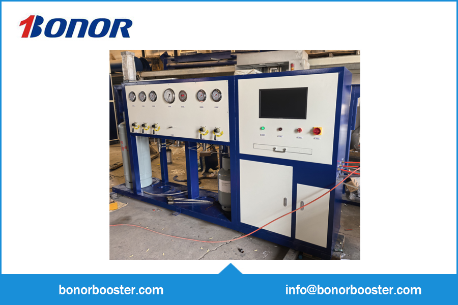
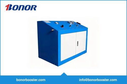
The LPG Cylinder Hydrostatic Testing Machine—hereinafter referred to as “the Equipment”—is designed for conducting hydrostatic pressure resistance tests on liquefied petroleum gas (LPG) cylinders. It is capable of performing pressure resistance tests on test specimens, with the test pressure, pressure-holding duration, and allowable pressure drop controlled by a computer system, thereby enabling automated parameter output.
The Equipment consists of several key components: a pressure-boosting circuit, a drive circuit, a water circulation circuit, and a test chamber.
II:Main Technical Parameters
- Test Medium: Water
- Pressure Control Range: 1–3.2 MPa
- Control Method: Computer-based PLC Control
- Sealing Method: Pneumatic Cylinder Clamping Seal
- Workstations: 5
- Test Specimens: 15-liter and 50-liter LPG Steel Cylinders
- Voltage: 220 V
III. Preparations
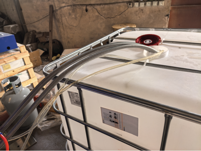
- Based on the user’s actual operating conditions, place the unit in a suitable location (expansion bolts may be used to secure the equipment).
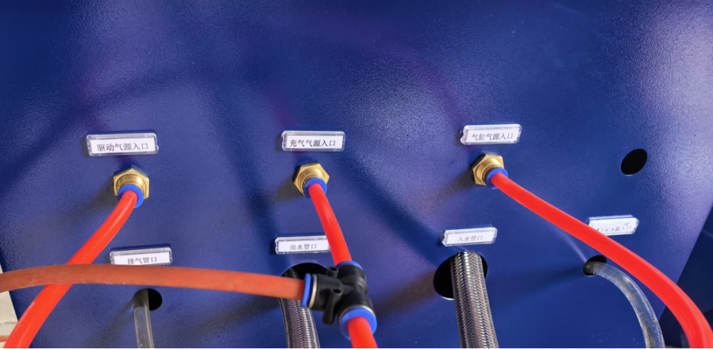
- Connect a pipeline from the air compressor to the drive air inlet (pressure: 0.6–0.8 MPa).
- Connect a pipeline from the air compressor to the inflation air inlet (pressure: 0.3–0.8 MPa).
- Connect a pipeline from the air compressor to the cylinder air inlet (pressure: 0.6–0.8 MPa).
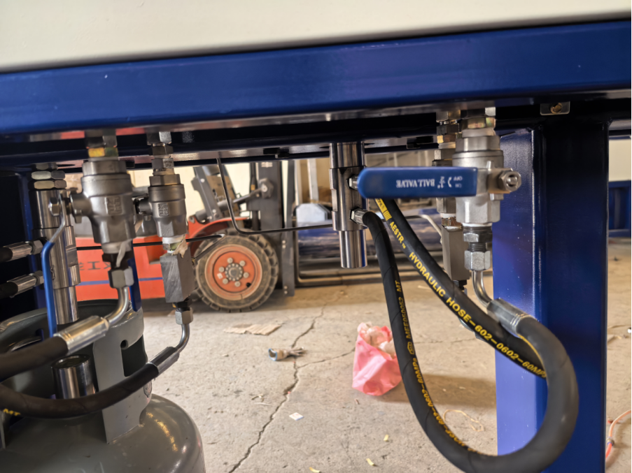
- The customer must provide a water tank of approximately 1 cubic meter (alternatively, a large pit or trough available on-site may serve as a substitute). Submerge the four water lines—specifically the equipment’s exhaust outlet, water outlet, water inlet, and booster pump water inlet—into this large water tank; ensure that the tank is positioned in close proximity to the equipment.
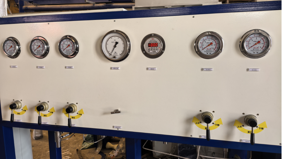
6.Before commencing the test, ensure that all valves are in the open position (the valve for the precision gauge may remain closed initially; it should be opened slowly only when pressure calibration is required. Note: When utilizing the precision pressure gauge, its associated valve must be opened slowly, and pressure must be released slowly thereafter; avoid rapid increases or decreases in pressure).
- Connect the power supply and air source, then switch on the main power switch. Fill the water tank to at least two-thirds of its capacity.
Water Pressure Test Operating Procedures
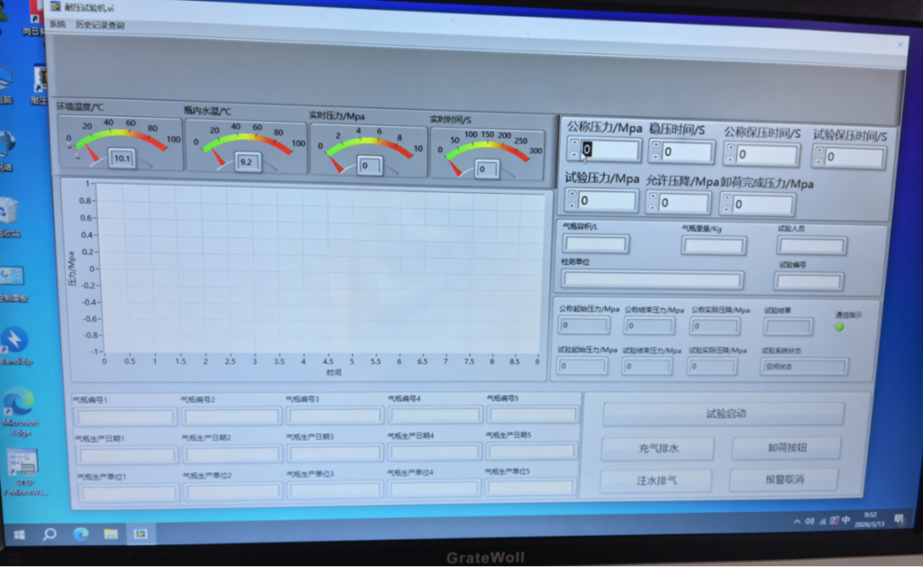
1.Turn on the computer, double-click the application shortcut on the interface, and enter the operation control interface.
- Place the prepared LPG cylinder to be tested onto the designated workstation, and insert the sealing fixture into the cylinder. For the initial test setup, ensure that the cylinder and the pneumatic ram are centrally aligned; then, secure the bottom positioning plate in place. Ensure that the orientation of the cylinder’s open end aligns with the position of the connecting hose to prevent any interference between the hose and the pneumatic ram during its upward or downward movement.
- Once the cylinder is aligned, select the specific workstation designated for the test. Rotate the manual lever valve to lower the pneumatic ram, thereby centering and pressing down firmly on the sealing fixture. Note that the sealing fixture is equipped with gaskets on both its upper and lower surfaces; ensure that all gaskets are properly installed before engaging the clamp. Once the pneumatic ram has securely clamped the fixture, return the manual lever valve to its reset position.
- Select the workstation designated for the test, and open the two manual valves associated with that specific station. Ensure that the manual valves at all other workstations remain closed.
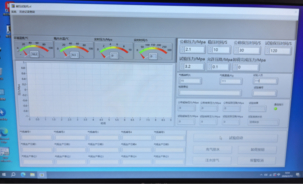
5.Click the “Water Filling and Venting” button to initiate the water-filling process for the gas cylinder. Monitor the vent line; once a continuous stream of water appears in the line, the filling is complete. Click the “Water Filling and Venting” button again to finalize the process. Wait until the system pressure drops to approximately 0 MPa, then click the “Unloading” button once to ensure the system is in a depressurized state prior to commencing the test.
- On the operation interface, enter parameters such as nominal pressure, pressure stabilization time (10 seconds recommended), nominal holding time, test pressure, test holding time, and allowable pressure drop. Click “Start Test”; the equipment will automatically pressurize to the nominal pressure, automatically hold that pressure for the set duration, then pressurize to the test pressure, automatically hold that pressure for the set duration, and finally automatically depressurize. The system will automatically generate a test report complete with a pressure curve.
- Click the “Vent/Drain” button to automatically drain the water from the gas cylinder. Once airflow is observed at the drain outlet, click the “Vent/Drain” button again to terminate the venting and draining process. At this point, residual pressure remains within the system; click the “Depressurize” button—continuing until no bubbles are visible in the exhaust line—to fully release the system pressure, then click the “Depressurize” button again to terminate the depressurization process.
- Before removing the gas cylinder, ensure absolutely that the system is free of any residual pressure. Then, turn the manual lever valve to the “Up” position to raise the hydraulic cylinder, and remove the gas cylinder. The test is now complete.
 |
 |
Usage, Maintenance Requirements, and Precautions
1.Add lubricating oil to the oil cup of the dual-unit assembly located inside the cabinet.
2.If the sealing gasket is damaged, it must be replaced immediately.
3.Avoid ground vibrations to prevent compromising the accuracy of the pressure gauge.
4.The precision gauge valve should be kept in a normally closed position; it should be opened slowly only when pressure verification is required. When using the precision pressure gauge, ensure that the valve is opened slowly and pressure is released gradually; do not allow the pressure to rise or fall too rapidly.
5.Before raising the cylinder, ensure that the equipment is completely depressurized; otherwise, the cylinder must not be raised.
Where a hydrostatic pressure test bench is used
Most hydrostatic benches are bought for one part family and end up testing five. The LPG Cylinder Hydrostatic Testing Machine is specified with that future in mind — shared pressure section, exchangeable fixtures, and software recipes per part family. This configuration is arranged around lpg cylinder: the fixture set, the hold logic and the report format are chosen for that job first.
- Hydraulic cylinder barrels — tube stock and finished barrels proof-tested to verify wall integrity.
- Hydraulic press and power-pack reservoirs — internal volumes proof-tested after fabrication and after repairs.
- Gas cylinder requalification stations — hydro testing with water jacket or weighing method, record per cylinder.
- LPG cylinder plants — periodic requalification and factory hydro with a stored record per serial number.
What makes this LPG Cylinder Hydrostatic Testing Machine practical is the way it handles the cylinder: one clamping routine, one pressurisation recipe and one result file, test after test.
What to specify before we build yours
- Output needed — a gauge reading, a printed certificate per part, or a data file with the full pressure curve. On this unit it is arranged for the cylinder.
- Media and water quality — fresh water, inhibited water, oil or glycol; stainless and galvanised parts need inhibition or a different medium. The setting here follows the cylinder you run most.
The way this particular bench is set up: The specification calls for test medium of water. On this machine control method is computer-based plc control. Here voltage is set to 220 v.
Choosing the right hydrostatic pressure test bench
A hydrostatic bench is a ten-year tool, so it pays to specify it for the work you will actually do, not the work you do today:
- Think about water treatment early. Untreated water leaves rust inside carbon steel parts and stains stainless ones. A simple filtration and inhibitor loop is far cheaper than re-cleaning a batch of parts.
- Size the pump for fill time, not just pressure. A large vessel at low pressure can take longer to fill than a small one at high pressure. Ask for the flow rate at your working pressure and calculate the cycle time before you commit.
- Fixture fit for the cylinder. The clamping set is drawn around your cylinder drawings first, so the part sits square without shimming — and the same fixture family extends to other sizes later.
Frequently asked questions
Do we need to treat the test water?
For carbon steel parts, yes at least minimally — inhibited fresh water prevents flash rust that customers complain about. Stainless and most alloys are more forgiving. If parts go straight from test to coating or shipping, a simple inhibitor dosing tank solves the problem cheaply. On this build the cylinder is the reference case, and the setting is proven with your samples at commissioning.
Can the bench test at very low pressures as well?
Yes, within the range of the selected instrumentation. The honest limit is resolution: a transducer sized for 32 MPa cannot resolve a meaningful drop at 4 MPa. That is why we quote instrumentation per range, and some customers order a second, low-range circuit for their small parts. The LPG Cylinder Hydrostatic Testing Machine is commissioned on your site with this point demonstrated on your own parts.
Related equipment and further reading
Every bench we quote starts from a real part list. Send yours and you get a costed configuration, not a generic price list, within one working day.